Network FundamentalsBefore you start managing a Solaris network, you need to know the definitions of some terms used in networking. There are numerous acronyms related to networking, and many of them are explained in the following sections. You'll first learn about the networking model that is deployed by Solaris 10, and then you'll learn about the types of networks that are available, including the various network protocols. Finally, you'll learn about the physical components of the network hardware, including the network interfaces and cables. Network TopologiesThe term network topology refers to the overall picture of the network and the arrangement in which the nodes on a network are connected to each other. The topology describes small and large networks, including local area networks (LANs) and wide area networks (WANs). LANsA LAN is a set of hosts, usually in the same building and on the same floor, connected by a high-speed medium such as Ethernet. A LAN might be a single Internet Protocol (IP) network or a collection of networks or subnets that are connected through high-speed switches and/or routers. The network interface, and cable or wire, used for computer networks is referred to as network media. Normally a type of twisted-pair wire or fiber-optic cable connects nodes on a LAN. Twisted-pair cable has less bandwidth than optical fiber, but it is less costly and easier to install. With twisted-pair cable, the two individual wires are twisted around each other to minimize interference from the other twisted pairs in the cable. Twisted pair cable is available in two different categories:
In addition, twisted-pair cable is available in stranded or solid wire (22 to 26 gauge). Stranded wire is used most commonly because it is very flexible and can be bent around corners. Solid wire cable suffers less attenuation (that is, signal loss) and can span longer distances, but it is less flexible than stranded wire and can break if it is repeatedly bent. Furthermore, cable is grouped into seven categories, according to the Electronic Industries Alliance/Telecommunications Industry Association (EIA/TIA) standard EIA/TIA-568, based on its transmission capacity. The categories are listed in Table 8.1.
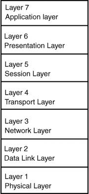
You can see from Table 8.1 that there are several variants of twisted-pair cable, each with different capacities. For example, Category 5 (Cat 5) UTP cable can support sustained data throughput of 100Mbps. WANsA wide area network (WAN) is a network that covers a potentially vast geographic area. An example of a WAN is the Internet. Another example is an enterprise network that links the separate offices of a single corporation into one network spanning an entire country or perhaps an entire continent. A WAN, unlike a LAN, usually makes use of third-party service providers for interconnection. It is a common misconception among newcomers to the world of networking that a WAN is simply a LAN but on a larger scale. This is not true because different technologies, equipment, and protocols are used in LANs and WANs. For example, Ethernet is a LAN technology that is not usually used in WANs (but this is changing with wider availability and lower cost of high-speed long-distance fiber connections). Network Protocols and Network ModelsA network protocol is the part of the network that you configure but cannot see. It's the "language" of the network, which controls data transmission between systems across the network. To understand protocols, you need to first understand network models. A network model is an abstract common structure used to describe communication between systems. The two network models that provide the framework for network communication and that are the standards used in Solaris network environments are the International Standards Organization (ISO)/Open Systems Interconnection (OSI) reference model and the Transmission Control Protocol/Internet Protocol (TCP/IP) model. These models are discussed in the following sections. The network models consist of different layers. You can think of the layers as steps that must be completed before the next step can be tackled, and before communication can occur between systems. The ISO/OSI ModelThe seven-layered ISO/OSI model was devised in the early 1980s. Although this model represents an ideal world and is somewhat meaningless in today's networking environment, it's quite helpful in identifying the distinct functions that are necessary for network communication to occur. In the ISO/OSI model, individual services that are required for communication are arranged in seven layers that build on one another. Each layer describes a specific network function, as shown in Figure 8.1. Figure 8.1. The seven-layer ISO/OSI model.
Table 8.2 describes the function of each individual layer. The TCP/IP ModelIn order for a network to function properly, information must be delivered to the intended destination in an intelligible form. Because different types of networking software and hardware need to interact to perform the network function, designers developed the TCP/IP communications protocol suite (a collection of protocols), which is now recognized as a standard and is used throughout the world. Because it is a set of standards, TCP/IP runs on many different types of computers, making it easy for you to set up a heterogeneous network running any operating system that supports TCP/IP. The Solaris operating system includes the networking software to implement the TCP/IP communications protocol suite. The TCP/IP model is a network communications protocol suite that consists of a set of formal rules that describe how software and hardware should interact within a network. The TCP/IP model has five layers: Exam Alert Four or Five LayersBe careful on the exam because Sun has used both a four-layer and five-layer description of this model since Solaris 8. If a question describes a four-layer model then the hardware layer should be thought of as being integrated with the network interface layer. Each of these is discussed in the following sections. The Hardware LayerThe TCP/IP model hardware layer corresponds to the ISO/OSI model physical layer and describes the network hardware, including electrical and mechanical connections to the network. This layer regulates the transmission of unstructured bit streams over a transmission medium, which might be one of the following:
Note Support for Token Ring has been removed in Solaris 10, as it is now considered an obsolete technology. For each medium, the IEEE has created an associated standard under project 802, which was named for the month (February) and year (1980) of its inception. Each medium has its own standard, which is named based on the 802 project. For example, Ethernet has its own standard: 802.3. The Network Interface LayerThe TCP/IP model network interface layer corresponds to the ISO/OSI data link layer; it manages the delivery of data across the physical network. This layer provides error detection and packet framing. Framing is a process of assembling bits into manageable units of data. A frame is a series of bits with a well-defined beginning and end. The network interface layer protocols include the following:
These protocols are described later in this chapter. The Internet LayerThe TCP/IP model Internet layer corresponds to the ISO/OSI network layer and manages data addressing and delivery between networks, as well as fragmenting data for the data link layer. The Internet layer uses the following protocols:
The Transport LayerThe TCP/IP model transport layer corresponds to the ISO/OSI model transport layer and ensures that messages reach the correct application process by using Transmission Control Program (TCP) and User Datagram Protocol (UDP). TCP uses a reliable, connection-oriented circuit for connecting to application processes. A connection-oriented virtual circuit allows a host to send data in a continuous stream to another host. It guarantees that all data is delivered to the other end in the same order as it was sent and without duplication. Communication proceeds through three well-defined phases: connection establishment, data transfer, and connection release. UDP is a connectionless protocol. It has traditionally been faster than TCP because it does not have to establish a connection or handle acknowledgements. As a result, UDP does not guarantee delivery. UDP is lightweight and efficient, but the application program must take care of all error processing and retransmission. Considerable improvements in network technology, however, have virtually eliminated the performance gap between TCP and UDP, making TCP the protocol of choice. The Application LayerThe TCP/IP model application layer corresponds to the session layer, presentation layer, and application layer of the ISO/OSI model. The TCP/IP model application layer manages user-accessed application programs and network services. This layer is responsible for defining the way in which cooperating networks represent data. The application layer protocols include the following:
Exam Alert Know Layers and FunctionsFor the exam, ensure that you are familiar with the layers of both the OSI seven-layer model and the TCP/IP model. You should be able to identify functions/protocols that operate at each layer and the order in which the layers are processed. Encapsulation and DecapsulationWhen you think of systems communicating via a network, you can imagine the data progressing through each layer down from the application layer to the hardware layer, across the network, and then flowing back up from the hardware layer to the application layer. A header is added to each segment that is received on the way down the layers (encapsulation), and a header is removed from each segment on the way up through the layers (decapsulation). Each header contains specific address information so that the layers on the remote system know how to forward the communication. For example, in TCP/IP, a packet would contain a header from the physical layer, followed by a header from the network layer (IP), followed by a header from the transport layer (TCP), followed by the application protocol data. PacketsA packet is the basic unit of information to be transferred over the network. A packet is organized much like a conventional letter. Each packet has a header that corresponds to an envelope. The header contains the addresses of the recipient and the sender, plus information on how to handle the packet as it travels through each layer of the protocol suite. The message part of the packet corresponds to the contents of the letter itself. A packet can contain only a finite number of bytes of data, depending on the network medium in use. Therefore, typical communications such as email messages are split into packets. EthernetEthernet is a standard that defines the physical components a machine uses to access the network and the speed at which the network runs. It includes specifications for cable, connectors, and computer interface components. Ethernet is a LAN technology that originally facilitated transmission of information between computers at speeds of up to 10Mbps. A later version of Ethernet, called 100BASE-T, or Fast Ethernet, pushed the speed up to 100Mbps, and Gigabit Ethernet supports data transfer rates of 1Gbps (1,000Mbps). Table 8.3 lists some common media names and their associated cable types.
Note 10BASE2 and 10BASE5 media are now very rarely used; even 10BASE-T networks are becoming increasingly rare. The 100BASE-T type of Ethernet is the most popular medium, but it is gradually being replaced by newer systems that support 1000BASE-T (gigabit) and a growing number of fiber-optic connected devices. Ethernet uses a protocol called CSMA/CD, which stands for Carrier Sense Multiple Access with Collision Detection. Multiple Access means that every station can access the single cable to transmit data. Carrier Sense means that before transmitting data, a station checks the cable to determine whether any other station is already sending something. If the LAN appears to be idle, the station can begin to send data. When several computers connected to the same network need to send data, two computers might try to send at the same time, causing a collision of data. The Ethernet protocol senses this collision and notifies the computer to send the data again. How can two computers send data at the same time? Isn't Ethernet supposed to check the network for other systems that might be transmitting before sending data across the network? Here's what happens in a 10Mbps network: An Ethernet station sends data at a rate of 10Mbps. It allows 100 nanoseconds per bit of information that is transmitted. The signal travels about 0.3 meters (1 foot) in 1 nanosecond. After the electrical signal for the first bit has traveled about 30 meters (100 feet) down the wire, the station begins sending the second bit. An Ethernet cable can run for hundreds of feet. If two stations are located about 75 meters (250 feet) apart on the same cable and both begin transmitting at the same time, they will be in the middle of the third bit before the signal from each reaches the other station. This explains the need for the Collision Detection part of CSMA/CD. If two stations begin sending data at the same time, their signals collide nanoseconds later. When such a collision occurs, the two stations stop transmitting and try again later, after a randomly chosen delay period. This also explains why distances are an important consideration in planning Ethernet networks. Although an Ethernet network can be built by using one common signal wire, such an arrangement is not flexible enough to wire most buildings. Unlike an ordinary telephone circuit, Ethernet wire cannot be spliced to connect one copper wire to another. Instead, Ethernet requires a repeater, a simple station that is connected to two wires. When the repeater receives data on one wire, it repeats the data bit-for-bit on the other wire. When collisions occur, the repeater repeats the collision as well. In buildings that have two or more types of Ethernet cable, a common practice is to use media converters, switches, or repeaters to convert the Ethernet signal from one type of wire to another. Network hardware is discussed in more detail later in the chapter. Note As of Solaris 10, the FDDI interface is no longer supported. Network HardwareThe network hardware is the physical part of the network that you can actually see. The physical components connect the systems and include the network interface cards (NICs), hosts, cable, connectors, hubs, and routers, some of which are discussed in the following sections. NICsThe computer hardware that allows you to connect a computer to a network is known as a network interface card (NIC), or network adapter. The network interface can support one or more communication protocols that specify how computers use the physical mediumthe network cable or the radio spectrumto exchange data. Most computer systems come with a preinstalled network interface. Each LAN media type has its own associated network interface. For example, if you want to use Ethernet as your network medium, you must have an Ethernet interface installed in each host that is to be part of the network. The connectors on the board to which you attach the Ethernet cable are referred to as Ethernet ports. HostsIf you are an experienced Unix/Solaris user, you are no doubt familiar with the term host, which is often used as a synonym for computer or machine. From a TCP/IP perspective, only two types of entities exist on a network: routers and hosts. When a host initiates communication, it is called a sending host, or sender. For example, a host initiates communications when the user uses ping or sends an email message to another user. The host that is the target of the communication is called the receiving host, or recipient. Each host has an Internet address and a hardware address that identify it to its peers on the network, and usually a hostname. These are described in Table 8.4. Hubs and SwitchesEthernet cable is run to each system from a hub or switch. A hub does nothing more than connect all the Ethernet cables so that the computers can connect to one another. It does not boost the signal or route packets from one network to another. When a packet arrives at one port, it is copied to the other ports so that all the computers on the LAN can see all the packets. Hubs can support from two to several hundred systems. A passive hub serves as a conduit for the data, allowing it to go from one device, or segment, to another. Intelligent hubs include additional features that let you monitor the traffic passing through the hub and configure each port in the hub. Intelligent hubs are also called manageable hubs. A third type of hub, called a packet-switching hub (or switch), is a special type of hub that forwards packets to the appropriate port based on the packet's destination address. A network that utilizes conventional hubs is a shared network because every node on the network competes for a fraction of the total bandwidth. In a shared network, data packets are broadcast to all stations until they discover their intended destinations; this wastes both time and network bandwidth. A switch remedies this problem by looking at the address for each data packet and delivering the packet directly to the correct destination, and this provides much better performance than the hub system. Most switches also support load balancing so that ports are dynamically reassigned to different LAN segments based on traffic patterns. Most switches are autosensing, which means they support both Fast Ethernet (100Mbps) and Gigabit Ethernet (1000Mbps) ports. This lets the administrator establish a dedicated Ethernet channel for high-traffic devices such as servers. In addition, some switches include a feature called full-duplex data transfer. With this feature, all computers on the switch can "talk" to the switch at the same time. Full-duplex data transfer also allows switches to send and receive data simultaneously to all connections, whereas a hub cannot. A hub simply works with one computer at a time and only sends or only receives data because it cannot handle simultaneous two-way communication. RoutersA router is a machine that forwards packets from one network to another. In other words, whereas a hub connects computers, a router connects networks. To do this, a router must have at least two network interfaces. A machine with only one network interface cannot forward packets; it is considered a host. Most of the machines you set up on a network are likely to be hosts. Routers use packet headers and a forwarding table, called a routing table, to determine where packets go. Routes can be either static (in which case they are preset by network/system administrator) or dynamic (in which case a route to a destination host is learned or calculated at the time that it is requested). IPv4 AddressingIn IPv4, each host on a TCP/IP network has a 32-bit network addressreferred to as the IP addressthat must be unique for each host on the network. If the host will participate on the Internet, this address must also be unique to the Internet. For this reason, IP addresses are assigned by special organizations known as regional Internet registries (RIRs). The IPv4 address space is the responsibility of Internet Corporation for Assigned Names and Numbers (ICANN; see www.icann.org). The overall responsibility for IP addresses, including the responsibility for allocation of IP ranges, belongs to the Internet Assigned Numbers Authority (IANA; see www.iana.org). An IP address is a sequence of 4 bytes and is written in the form of four decimal integers separated by periods (for example, 10.11.12.13). Each integer is 8 bits long and ranges from 0 to 255. An IP address consists of two parts: a network ID, which is assigned by an RIR, and a host ID, which is assigned by the local administrator. The first integer of the address (10.0.0.0) determines the address type and is referred to as its class. Five classes of IP addresses exist: A, B, C, D, and E. The following sections briefly describe each class. Note IPv6 Due to limited address space and other considerations of the IPv4 scheme, a revised IP protocol is gradually being made available. The protocol, named IPv6, has been designed to overcome the major limitations of the current approach. IPv6 is compatible with IPv4, but IPv6 makes it possible to assign many more unique Internet addresses and offers support for improved security and performance. A brief section on IPv6 appears later in this chapter for background information, even though it is not a specific objective in the Solaris 10 Part II exam. Class A AddressesClass A addresses are used for very large networks with millions of hosts, such as the Internet. A Class A network number uses the first 8 bits of the IP address as its network ID. The remaining 24 bits make up the host part of the IP address. The value assigned to the first byte of a Class A network number falls within the range 0 to 127. For example, consider the IP address 75.4.10.4. The value 75 in the first byte indicates that the host is on a Class A network. The remaining bytes, 4.10.4, establish the host address. An RIR assigns only the first byte of a Class A number. Use of the remaining 3 bytes is left to the discretion of the owner of the network number. Only 126 Class A networks can exist because 0 is reserved for the network, and 127 is reserved for the loopback device, leaving 1 to 126 as usable addresses. Each Class A network can accommodate up to 16,777,214 hosts. The 10.x.x.x network is reserved for use by private networks for hosts that are not connected to the Internet. If you want to assign a Class A network and you are not visible on the Internet, you can use one of these network addresses. Class B AddressesClass B addresses are used for medium-size networks, such as universities and large businesses with many hosts. A Class B address uses 16 bits for the network number and 16 bits for the host number. The first byte of a Class B network number is in the range 128 to 191. In the number 129.144.50.56, the first 2 bytes, 129.144, are assigned by an RIR and make up the network address. The last 2 bytes, 50.56, make up the host address and are assigned at the discretion of the network's owner. A Class B network can accommodate a maximum of 65,534 hosts. Again, the first and last addresses on the network are reserved. The 0 host address is reserved for the network, and the 255 address is reserved as the IP broadcast address. Therefore, the actual number of hosts that can be assigned on a Class B network is 65,534, not 65,536. The network address ranges 172.16.x.x through 172.31.x.x are reserved for use by private networks that are not connected to the Internet. If you want to assign a Class B network and you are not visible on the Internet, you can use one of these network addresses. Class C AddressesClass C addresses are used for small networks with fewer than 254 hosts. A Class C address uses 24 bits for the network number and 8 bits for host number. A Class C network number occupies the first 3 bytes of an IP address; only the fourth byte is assigned at the discretion of the network's owner. The first byte of a Class C network number covers the range 192 to 223. The second and third bytes each cover the range 0 to 255. A typical Class C address might be 192.5.2.5, with the first 3 bytes, 192.5.2, forming the network number. The final byte in this example, 5, is the host number. A Class C network can accommodate a maximum of 254 hosts out of 256 addresses; again, this is because the first and last values are reserved. The 192.168.x.x network ranges are specially reserved for private networks that are not connected to the Internet. If you want to assign a Class C network and you are not visible on the Internet, you can use one of these network addresses. Class D and E AddressesClass D addresses cover the range 224 to 239 and are used for IP multicasting, as defined in RFC 988. Class E addresses cover the range 240 to 255 and are reserved for experimental use. Planning for IP AddressingThe first step in planning for IP addressing on a network is to determine how many IP addresses you need and whether the network is going to be connected to the Internet. If the network is not going to be connected to the Internet, you could choose addresses in the 10.x.x.x, or 172.16.x.x172.31.x.x, or 192.168.x.x range. For networks that are going to be connected to the Internetand hence visible to the rest of the worldyou need to obtain legal IP addresses; this is necessary because each host on a network must have a unique IP address. IP addresses can be obtained either through an Internet service provider (ISP) or an RIR, as mentioned earlier in this section. When you receive your network number, you can plan how you will assign the host parts of the IP address. Your nearest RIR depends on where, geographically, your network is located. The current list of RIRs is as follows:
After you contact the correct RIR, you have to justify why you should be given global IP addresses. Normally, unless yours is a large organization, you would be expected to obtain IP addresses from your ISP. Note Being Careful with IP Addresses You should not arbitrarily assign network numbers to a network, even if you do not plan to attach your network to other existing TCP/IP networks. As your network grows, you might decide to connect it to other networks. Changing IP addresses at that time can be a great deal of work and can cause downtime. Instead, you might want to use the specially reserved IP networks 192.168.x.x, or 172.16.x.x172.31.x.x, or 10.x.x.x for networks that are not connected to the Internet. IPv6Tip IPv6 No questions on the exam relate to IPv6. This section is included purely for background information. As the Internet community continues to grow and use more IPv4 addresses, we have been running out of available IPv4 addresses. IPv6, also called IP Next Generation (IPng), improves Internet capability by using a simplified header format, longer addresses (128 instead of 32 bits), support for authentication and privacy, autoconfiguration of address assignments, and new Quality of Service (QoS) capabilities. Specifically, IPv6 provides these enhancements:
Note
IPv6 increases the IP address size from 32 bits to 128 bits, to support more levels of addressing hierarchy. Thus, the number of potential addresses is 4 billion x 4 billion x 4 billion times the size of the IPv4 address space. Here's an example of an IPv6 address: 2001:0DB8:0000:0000:0000:FFFF:ACBC:19A1 The first 48 bits of the address represent the public topology. The next 16 bits represent the site topology.
|