Previous Section  < Day Day Up >  Next Section

2.2 Dissecting a Network Packet

A network packet is nothing more than a chunk of data that an application wants to deliver to another system on the network. This chunk of data has information added to the front and back that contains instructions for where the data needs to go and what the destination system should do with it once it arrives. The addition of this routing and usage information is called encapsulation.

The TCP/IP model uses four layers of encapsulation, also referred to as a stack or an IP stack. A packet is something like Russian Matroishka or "nesting" dolls: painted wooden figurines that hold smaller versions of themselves. Each doll is slightly smaller than the parent into which it is placed. The smallest doll, which cannot be opened, is the actual application data. Each larger, enclosing doll represents the header data affixed to the original content. The insertion and removal of each layer of a Matroishka doll is equal to a network-level header being added or removed from a packet.

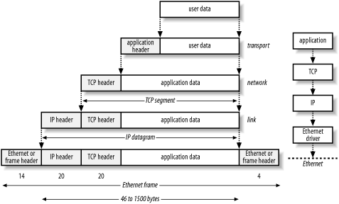
Figure 2-2 illustrates the process. We start with a chunk of application data, to which we add a header. We take that data (application data plus application header) and package it up as a series of TCP segments by adding TCP headers. We then add an IP header to each TCP segment, making IP datagrams. Finally, we add Ethernet headers and trailers to the IP datagrams, making an Ethernet frame that we can send over the wire. Each layer has its own function: TCP (the transport layer) makes sure data gets from point A to point B reliably and in order; IP (the network layer) handles routing, based on IP addresses and should be familiar to you; and Ethernet (the link layer) adds low-level MAC (media access control) addresses that specify actual physical devices. It's also important to note that there are several choices at each layer of the model: at the transport layer, you can see either TCP, UDP, or ICMP. Each layer of the network stack is unaware of the layers above and below. The information coming from the layers above are simply treated as data to be encapsulated. Many application protocols can be packed into TCP. When the packet is received at its final destination, the same process is repeated in reverse. The packet is de-encapsulated and the headers stripped off when it is received by the intended target.

Figure 2-2. User data is encapsulated with headers from each layer
figs/snrt_0202.gif


Most alerts generated by Snort are the result of matching strings inside the data payload of the packet, but many others are generated by the headers—most commonly the IP and TCP headers.

2.2.1 The IP Header

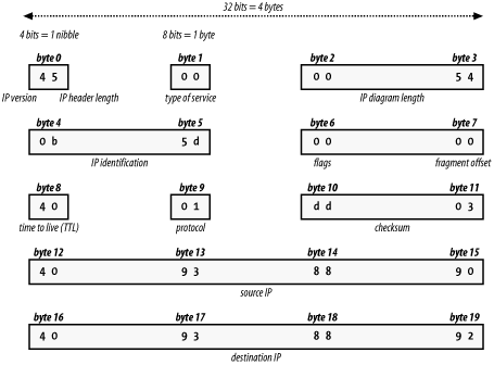
Primarily, the IP header specifies where the packet is going and where it came from. The IP header (Figure 2-3) is 20 bytes long and contains the following information:


IP version

Specifies either Version 4 or Version 6. Version 4 is what 99.9% of the Internet uses; Version 6 is outside the scope of this book.


IP header length

Specifies the total datagram header length in 32-bit words.


Type of service

Specifies how an upper-layer protocol would like a current datagram to be handled. Also assigns importance levels. For instance, you can request be sent with minimal delay or that the conversation use maximum throughput. These are fairly specialized and usually ignored by network devices.


Total length

The length, in bytes, of the entire packet, including the headers and the data.


Identification

Identifies the current datagram. Packets can fragment on slower network connections; this information is used to piece the fragments back together.


Flags

This field is only three bits long—and only first two are used. Bit one indicates whether the packet can be fragmented. Bit two indicates if the packet is the last packet in a series of fragmented packets.


Fragment Offset

Indicates where in the series of fragmented packets this packet is positioned. Some attackers will attempt to confuse network devices or IDS systems by setting this value to an unlikely or impossible value.


Time to live (ttl)

Maintains a counter that gets decremented every time the datagram passes through a network hop (router or firewall). When the counter reaches zero, a "destination unreachable" ICMP packet is returned to the sender. This keeps the packet from wandering the network forever.


Protocol

Indicates which upper-layer protocol is to receive the incoming packet on the receiving end (i.e., TCP, UDP).


Header checksum

Ensures the header's integrity. Really a transmission check, not a security feature.


Source address

Specifies the IP address of the sending system.


Destination address

Specifies the IP address of the receiving system.

Figure 2-3. The IP header: four bytes per row
figs/snrt_0203.gif


2.2.2 The TCP Header

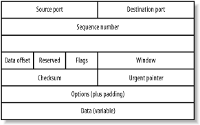
The TCP header is used to inform the receiving machine which upper-layer application should receive the data and information related to the establishment, maintenance, and tear down of TCP connection-oriented conversations. The TCP header (Figure 2-4) is of variable length and contains the following information:


Source port and destination port

Identifies the numbered port on which an upper-layer application is listening for data.


Sequence number

Usually specifies the number assigned to the first byte of data in the current message. In the connection-establishment phase, this field also can be used to identify an initial sequence number to be used in an upcoming transmission.


Acknowledgment number

The sequence number of the next packet that the sender expects to receive


Data offset

Indicates the beginning point of the data payload in the packet—essentially, the size of the header in 32-bit words.


Reserved

Not used and reserved for future use.


Flags

Contains information like the SYN, ACK, and FIN bits used in connection establishment and teardown.


Window

Specifies the size of the sending machine's receive window


Checksum

Ensures the header's integrity. Again, this is not really a security feature, but an integrity feature.


Urgent pointer

Points to the first urgent data byte in the packet


Options

Used (although not commonly) to designate preferences for flow control, routing, and compression of the packet. Can also be used to indicate a government or commercial security classification (like Top Secret, Classified, and so on). These fields are often used for experimental purposes. Different operating systems use these fields in different ways, making this field a source of false positive alerts.


Data

Contains data for upper-level applications that perform work on the packet's actual data payload (like IPSEC and encryption applications).

Figure 2-4. The 12 fields of a TCP header
figs/snrt_0204.gif


    Previous Section  < Day Day Up >  Next Section