2.9. NetworkingThe classic seven-layer OSI model has lately been replaced by the easier-to-understand four-layer TCP/IP model. To understand what role the network plays in the architecture of our application, we need to understand these four layers and how they interact with one another. The four layers form a simple stack, shown in Figure 2-2. Figure 2-2. The TCP/IP stack (photo by minky sue: http://flickr.com/photos/kukeit/8295137)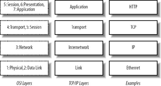 The bottom layer represents both the physical medium over which the signal travels (raido waves, pulses in a twisted pair cable, etc.) and the format used for encoding data in the medium (such as Ethernet frames or ATM cells). At the Internetworking layer, we start to deliver messages between different networks, where frames or cells get wrapped up into the familiar IP packets. On top of the Internetwork sits the transport, which is responsible for ensuring messages get from one end of the connection to the other reliably (as with TCP) or not (as with UDP). The final layer is where all the application-level magic starts to happen, using the preceeding layers to create a meaningful experience. Each layer sits on top of the layers below it, with data conceptually flowing only from one layer to the next. In a simple example where two computers are on the same network, a message being passed looks something like Figure 2-3. A message starts at the top of the stack, an HTTP request in this example, and descends through the layers, being gradually wrapped in larger and larger encapsulations (the IP packet encapsulates the HTTP request and the Ethernet frame encapsulates the IP packet). When the message hits the bottom of the stack, it moves over the wire as electrical, light, microwave, or similar signals, until it hits the bottom of the next stack. As this point, the message travels up the stack, being unwrapped at each layer. When the message reaches the top of the second stack, it's presented as an HTTP request. The key to this architecture is that the layers don't need to know what's below them. You can perform an HTTP request without caring about how IP works. You can create an IP packet without worrying how that packet will be sent as electrical signals in a copper cable. Figure 2-3. HTTP messaging through the TCP/IP stack(photo by minky sue: http://flickr.com/photos/kukeit/8295137)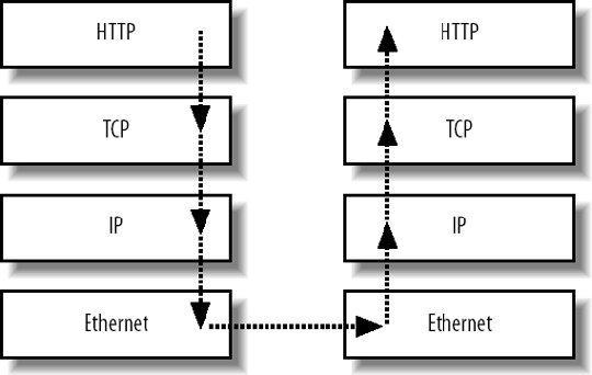 While our web servers and clients operate on all four layers of this stack, network devices can operate on anything between a single layer and the full four. Repeaters (which we seldom see in modern setups), hubs, and switches operate only on the bottom layer. Routers operate on layers 1 and 2, and sometimes higher. Load balancers, which we'll look at in Chapter 9, typically operate in either layers 1-3 (layer 4 balancing, using the OSI numbering system) or layers 1-4 (layer 7 balancing, again using the OSI numbering system). For each of these devices, messages still flow all the way to the top of the available stack, as shown in Figure 2-4. With a regular IP router, a message comes in over the network medium and is translated from an electrical signal to an Ethernet frame. We unpack the Ethernet frame, extract the IP packet, and pass it up the stack. We then look at the packet headers and decide if it needs routing (if the IP address falls on a different interface than the one that received the message). If we need to route the packet, we set the correct headers, and pass it back down the stack. The link layer wraps the new packet in a frame and passes it down to the wire to be transmitted to its destination host. As a message moves across the Internet, it moves up and down the stacks of many devices, each of which decides how to pass the message along until it reaches its destination. The distinction between devices and the layers they operate on is an important one, especially in understanding the different roles that switches, routers, and load balancers play. It's worth spending a little time researching general network fundamentals to get a good grasp on how things are put togetherthe TCP/IP model plays an important part, with everything else sitting on top. For Ethernet and IP-based networks, it's worth reading up on collision domains, ARP broadcast domains, multicast broadcast domains, multicast in general, and the various routing protocols, especially RIP and BGP. The literature often refers to the seven-layer OSI model, so understanding the overlap of the two is important. Figure 2-4. A message passing through the TCP/IP stack, with routing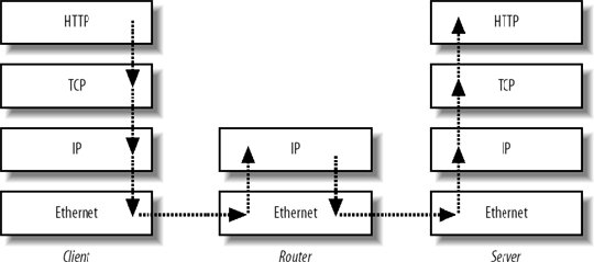 The main statistic you'll generally be interested in is how much data you can push across your network before reaching capacity. This depends on a number of factors, including the speed of your link layer, the type of traffic you're sending, the existence of network hardware in the path between machines, the broadcast domains, broadcast traffic, and the speed of your devices. The last item is particularly important, as a seven-layer network device with a 1 Gbps data link might not be able to handle a full gigabit of traffic if layer 7 processing is done in software. Layer 7 devices with ASICs, however, may be able to keep up fine. The maximum speed of data being pushed around your network takes many factors into account, not just the raw speed of the underlying link layer technology. This is often all academic, however (assuming you correctly configure your network to avoid broadcast storms), because most applications will not saturate a 1 Gbps link. There are exceptions to this for specialized network-intensive applications. We'll look at ways to scale out networks above the simple flat model in Chapter 9. |